Crucial CT16G4SFD824A RAM works in the Synology DS1819+

[Update 2021-02-06] I finally got around to purchasing a new 16GB stick, and I’m now successfully running 32GB in my Synology 1819+.

[Update 2020-04-20] My Synology has been responding slowly during FCPX edits, so I decided to revisit the RAM that I purchased. It turns out that one of the two 16GB sticks must be bad because I tried the 16+4 stick setup as mentioned earlier, and it wouldn’t boot. I tried the other 16GB stick and it booted quickly. Annoying. The problem was a bad stick all along.

Below is the original post from 18 Dec 2019.

I recently bought two sticks of Crucial 16GB DDR4-2400 SODIMM 1.2V CL17 non-ECC RAM (CT16G4SFD824A) hoping that I could upgrade my Synology DS1819+ from 4GB to 32GB. Unfortunately, when both sticks of the RAM are installed, the NAS doesn’t boot, and instead simply blinks the power light indefinitely (even after waiting 45min).

I did find that when I installed one 16GB stick alongside the existing 4GB stick, the system would boot, recognize the stick and report 20GB of RAM, but it also gave the warning about non-Synology RAM. I’m guessing this is because the RAM I purchased was non-ECC, whereas the Synology RAM is ECC.

For now, I’m returning to my 4GB configuration.

adif.plugin = Korg USB MIDI driver

[Update 2019-12-14] According to the macOS Catalina support for KORG/VOX Products article on the Korg website, the default Apple driver with macOS Catalina will support the device. The article gives instructions for removing the old driver.

Background

macOS Mojave is giving warnings about 32-bit software as the next version, which is macOS Catalina, will no longer support 32-bit software.

I’ve been able to determine what software relates to each warning except for one – “adif.plugin”. No amount of Googling helped (I don’t have any amateur radio software installed), but I finally figured it out today. To help others who might be Googling for this, here is the answer.

It belongs to the Korg USB MIDI driver that was installed to provide MIDI support to some piece of Korg hardware. In my case, it was the nanoKONTROL2, but the driver is generic and used for a lot of their hardware.

The last update for macOS (as of this writing) is version 1.2.5 r2 released on 2019-02-21. I don’t know if there are plans for a new version, but hopefully anyone searching for “adif.plugin” will now know that it is used for Korg USB MIDI.

If you want to verify this yourself, you can with these steps.

  1. Open Finder
  2. Go to the /System/Library/Extensions/adif.plugin folder using the Go > Go to Folder menu, or ⇧⌘G keyboard shortcut.
  3. Open the context menu for adif.plugin (right click or Ctrl-click) and select Show Package Contents.
  4. Inside the Contents folder will be an Info.plist file. Hit the space-bar to preview the file. You will see references to Korg USB MIDI listed.

The Starlane WID-B data logger

TL;DR I recently purchased and installed a Starlane WID-B data logger in my 2012 BMW S100RR so that I could improve my lap times at the track. I created two videos to share my experiences with others.

I’m an avid motorcycle rider, and enjoy improving my performance and lap times while riding at the track. I also work as an SRE (Site Reliability Engineer) in a large production computing environment. I’m primarily focused on backend systems, where performance (i.e. latency) is critical. To improve performance of computing systems, or just about anything for that matter, it must be measured.

For the last couple of years, I’ve looked for a reasonably priced data logger for my 2012 BMW S1000RR. BMW provides one, but I wasn’t keen on giving out USD 1000+ for the HP Parts Race Datalogger. I am only a track day rider, and no professional.

After quite a bit of research I learned that Starlane, the maker of my CORSRO-R GPS, produces WID (Wireless Input Device) device modules that collect signals from the bike. Searching for real-life experience information for these devices was basically impossible though. In the end, I chose to buy the WID-B from Starlane Germany.

In order to share some real-life experience with the Starlane WID-B, I filmed my first YouTube videos and shared them with the world. Perhaps this will encourage other track riders out there to install one of their own to improve their own lap times.

Using a TC Electronic DBMax for live streaming

This post describes using a TC Electronic DBMax to enhance the audio of a live stream.

In a live streaming situation, control of audio levels is critical to providing listeners and viewers with a great auditory experience. Inconsistent levels, or levels that are too loud or too soft result in a suboptimal experience, which degrades the performance.

The TC Electronic DBMax (Digital Broadcast Maximizer) is an ideal device for stabilizing and enhancing audio for live streaming and live recording situations. It supports up to three pre-dynamic inserts (AGC, Parametric EQ, 90 deg. mono, Dynamic Equalizer, Stereo Enhance, Normalizer, MS Decoding and MS Encoding), an expander, compressor and limiter, and a single post-dynamic insert (Transmission Limiter or Production Limiter). The EQ, compressors, and limiters are all 5-band, and provide broadcast quality results. It is basically a Finalizer 96K on steroids.

This image has an empty alt attribute; its file name is DBMAX-INCL.-DIGITAL-BYPASS-BROADCAST-MAXIMIZER-II_P0CXM_Front_L.png

In my role as recording lead at ICF, I use two separate DBMax devices to solve two separate problems. 1) stabilize the FoH signal for video, and 2) boost the stabilized signal for streaming. Once I put these two devices in, the video team I work with thanked me multiple times as they have a stable audio level they can rely on for single every event, no matter what kind of event, and they love the audio quality.

The first DBMax balances audio levels between a live worship session, where audio levels during worship are 10–15dB louder than the normal speaking volumes, and speaking sessions. The goal is to provide a signal that roughly meets the -23 LUFS broadcast standard in Europe, which means the audio recorded for video needs no additional post-processing for release to public TV (which we do for special events).

  • The feed coming from the FoH board is limited (with the Waves L2 Ultramaximizer), which provides a known maximum audio level.
  • The first insert is the Normalizer, which gives a small 3dB boost to the the overall audio level. The focus is to bring speaking parts into a better working range for later processing.
  • The second insert is the AGC (Automatic Gain Controller), which automatically raises the volume by up to 3dB (for soft speaking), or reduces it by up to -20dB (for loud band numbers).
  • The third insert is Stereo Enhance. The FoH provides signal for the main audience, but the stereo image in a live situation is typically reduced so that audience members on the far left/right sides don’t hear only a mono left or right signal. This insert provides a wider and more natural signal for TV viewing.
  • The 5-band expander is not used.
  • The 5-band compressor does a decent amount of compression, typically several DB. The advantage of a 5-band compressor is that kick and tom hits will not result in the overall signal being compressed, giving a more transparent sound.
  • The 5-band limiter catches loud peaks that might have made it past the compressor and AGC.
  • The last insert is the Production Limiter, which limits the overall sound signal. It is rarely triggered, and is mostly there to catch anything left.

The second DBMax takes the audio from the first DBMax, and boosts it to roughly -14 LUFS for live streaming on internet, and for streaming to TVs throughout the building (e.g. for parents in the children’s area). The -14 LUFS level was chosen as both YouTube and Apple both use this standard, and signals recorded from this DBMax require no additional post-processing for release to those streaming platforms (for video or podcasts).

  • The first insert is the Parametric EQ, which boots the signal 9dB, and applies a shallow high-pass and low-pass filter to strip off extra energy that laptop speakers and most headphones cannot reproduce.
  • The second insert the Spectral Stereo Image, which widens signals above 50 Hz, making for a better experience on headphones or laptops.
  • The third insert is the AGC, which makes minor signal adjustments of ±3dB to produce more consistent results.
  • The 5-band expander is not used.
  • The 5-band compressor provides fast and light 2.0:1 compression, and a 3.9 dB boost.
  • The 5-band limiter catches loud peaks that might have made it past the compressor.
  • The last insert is the Production Limiter, which limits the overall sound signal. It is rarely triggered, and is mostly there to catch anything left.

For those who are curious, the DBMax introduces roughly a 5ms delay into the audio signal chain, which must be compensated for when aligning the audio and video signals together. The video signals I’m working with have an 80ms latency delay, so I apply an additional 75ms delay using a Behringer X32 console, which was a console already available to me.

If you are interested in buying a used DBMax, they can frequently be found on eBay in the $700–1500 price range. New they are $4000+, so the used price is quite good. With patience, I’ve purchased three in the $700-$800 range. Try to purchase a device with the v2.60 or v2.90 firmware as the v2.02 firmware has a several minor issues that were fixed in the v2.60 release.

If you’d like to know more, let me know in the comments. For the actual settings, see this Google spreadsheet.

Additional Resources

Willow Creek FAQ: Broadcast Audio Process. This article describes how Willow Creek uses the DBMax.

Upgrading TC Electronic DBMax firmware

This post provides steps for updating TC Electronic DBMax firmware.

The latest firmware (v2.90) along with installation instructions are available from the tc electronic Music Tribe site. The instructions only describe using a M5000, which I don’t have, so I needed another solution.

[Update 2020-05-31] The firmware link no longer seems to work, so I’ve uploaded the dbmv290.zip firmware to this site.

The DBMax has a built-in PCMCIA card reader for storing settings, and which can be used to upgrade the firmware. According to the manual, the DBMax supports Type 1 PCMCIA cards with a minimum of 64KB SRAM and a maximum of 2 MB. Although settings can also be stored and recalled via MIDI, the firmware can only be updated via PCMCIA.

TC Electronic devices interact with the PCMCIA card as a raw storage device, and do not utilize a filesystem such as FAT. This means that the firmware must be copied as raw data to the device using software capable of doing so.

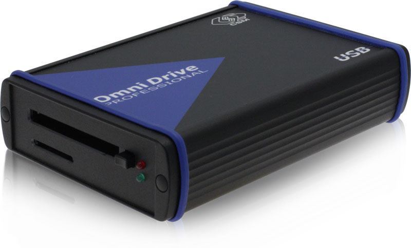
The solution I’ve found for copying the firmware to a PCMCIA card with a CSM OmniDrive USB2 Professional PCMCIA card reader. Unfortunately, PCMCIA cards are no longer common as they once were, and finding a drive proved to be both difficult, and expensive ($350 on eBay), but it works. Alternatively, an old laptop with a PCMCIA card reader should work, or with a TC Electronic M5000 (not the M5000X) and a 3.5″ floppy drive.

OmniDrive USB LF SD
OmniDrive USB LF SD

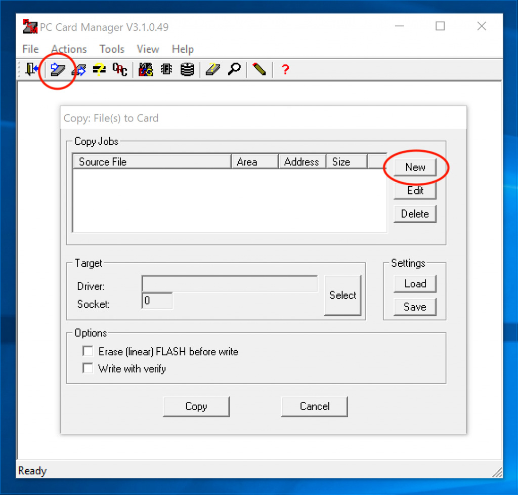
The OmniDrive site provides downloads for Windows which include a Software Driver (v3.3.4) that enables reading/writing of a PCMCIA card as a normal drive, and PC Card Manager (PCM) (v3.1.1) which enables reading/writing of a PCMCIA card as a raw storage device. The PC Card Manager is required for updating firmware.

To copy the firmware to the PCMCIA card…

  1. Unzip the dbmv290.zip file, which should provide a dbmv290.wiz file.
  2. Open the PC Card Manager software.
  3. Click the “Copy file(s) to a PC Card” icon.
  4. Select “New” to start a new Copy Job.
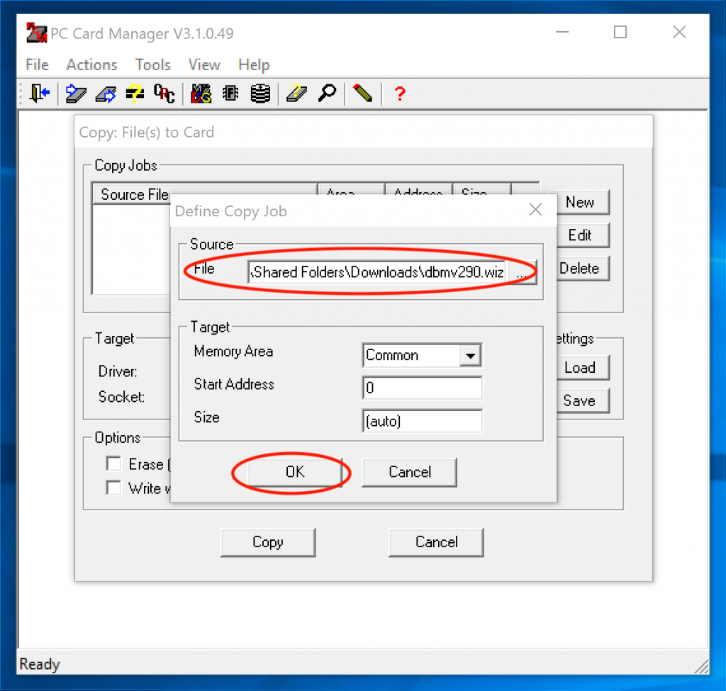
  5. Choose the dbmv290.wiz file as the Source File, and click “OK”. If the file isn’t listed, make sure file dialog is showing “All files”, not just “Images (*.PCC;*.PCA)” files.
  6. Click “Copy”. This should take <1 second.

To copy the firmware to the DBMax…

  1. Insert the PCMCIA card into the DBMax.
  2. Power the DBMax on while holding the “Help” button.
  3. Press the “OK” button to initiate the firmware upgrade. This should take <10 seconds.
  4. Power cycle the device.

That’s it!

Avid S3L and 3rd-party AVB Devices

This article describes how to connect and use MOTU AVB audio interfaces with the Avid S3L-X console.

[Update: 2021-03-22] I recently released a video on YouTube that demonstrates this. See my [Vlog] HOWTO Connect a MOTU AVB Device to the Avid S3L blog entry for more information.

For years, I have wanted to connect my MOTU AVB audio interfaces to my Avid S3L console, but have had no luck. After recently finding some information on the internets, I’ve found a way to reconfigure the S3L to talk using 8-channel AVB streams, which my MOTU devices require, and with some effort I now have bi-directional audio working!!

I’ve written up a document, and shared it as a public Google doc. I’ll eventually write it up here, but don’t feel like messing with WordPress right now.

Avid S3L-X and 3rd Party AVB (a Google Doc)

I’ve also started collecting data as I discover it in a wiki (https://wiki.forestent.com/Avid_S3L).

I look forward to any feedback!!

Testing Phantom Power

I’m the proud owner of an Earthworks M30 30kHz measurement microphone, which I use it to measure and calibrate sound systems using Smaart v8 from Rational Acoustics, along with a MOTU UltraLite mk3 audio interface.

Background

A few of years ago, I was attempting to measure a system, but had the strange behavior that after 15s or so, the signal from the microphone faded away completely, making it impossible to calibrate the system. I eventually realized that by swapping the 10m XLR cable I was using for a 3m cable, the problem went away.

As I’d used the setup without issue in the past, I assumed the issue was the with the particular XLR cable itself, but eventually realized that the longer cables produced hit-and-miss results, and that I needed to dig deeper into the problem. I also realized that I had always connected the mic through the console of the system I was measuring (to ensure I was calibrating the full path), but on this occasion I was calibrating directly with the interface as customers were expected to provide their own console, and only the system was a fixed installation.

As my father has decades of experience in audio, he was my first source for troubleshooting. He suggested that the mic had a high impedance, and that the 10m cable would cause issues with such a high impedance. Contacting MOTU, they also suggested that the mic might be the issue. The M30 model I own is a 600Ω impedance model which I’ve owned for 7y+.

With this information, I contacted Earthworks directly. After some discussion of the issue via email, Earthworks suggested that the impedance of the older M30 models might only be part of the issue, and that my audio interface might not be capable of maintaining 48V phantom with the longer cables. They provided me with a test procedure which I could use to verify my setup experimentally.

Testing

Phantom power test procedure

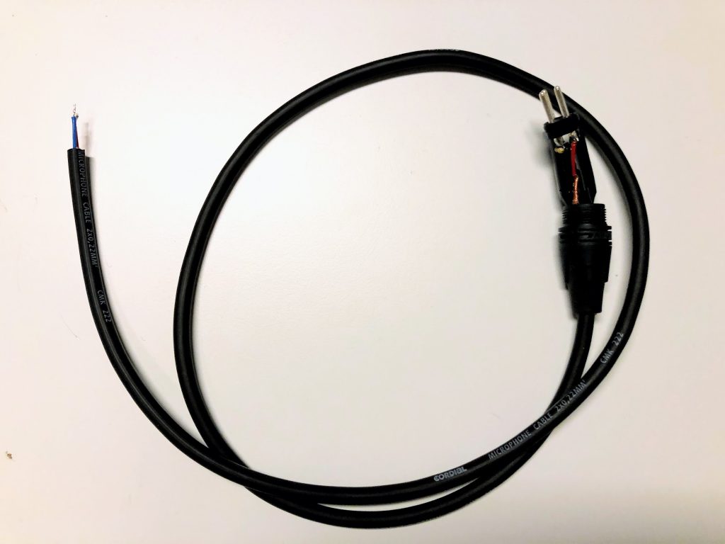
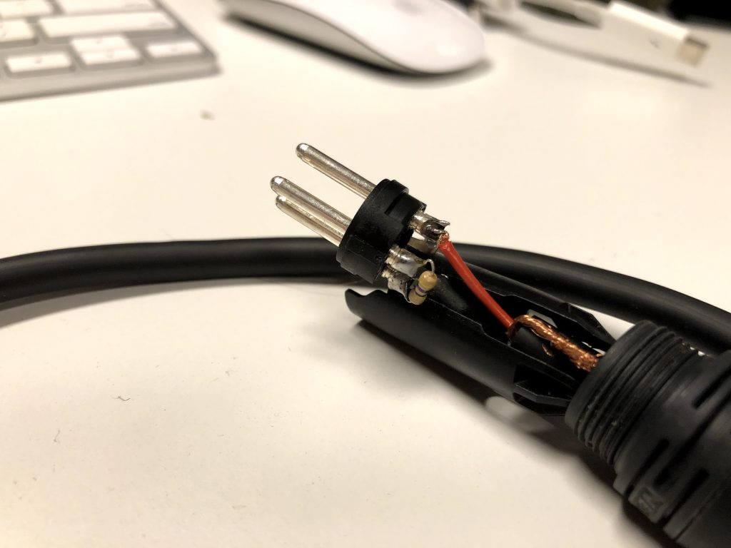
To perform the tests, I needed to build a cable. As I didn’t have a 47Ω resistor, I used a 50Ω resistor instead as it was close enough.

Rather than only check my UltraLite mk3, I set about testing the phantom power every XLR mic inputs that I had available to me at home at the time. I studied Physics in university, and doing experiments like this interest me!

The results below are based on the various document sections of the test procedure.
1.A. Measure voltage between pins 1 (neg) and 2 (pos). Expect 48V DC (±1V).
1.B. Measure voltage between pins 1 (neg) and 3 (pos). Expect 48V DC (±1V).
2.B. Measure current between resistor and pin 2. (47Ω resistor across pins 1 & 3; 47Ω resistor from pin 1). Expect >= 6.2 mA.
2.C. Measure voltage from above. Expect close to 48V DC.

1.A (V)1.B (V)2.B (mA)2.C (V)
Avid S3L-X E3 Engine48.2548.28747.59
M-Audio ProFire 610 (FireWire)49.4849.49748.17
Mackie 802VLZ447.3347.34746.8
MotU 828mk348.0148.01541.8
MotU UltraLite mk3 (FireWire)48.348.31541.5
MotU UltraLite mk3 (external)48.348.31542.16
MotU UltraLite AVB4949.05631.8

Results

The clear result was that none of my MotU devices were not capable of providing phantom power necessary to drive my Earthworks M30 mic.

After presenting the results to Earthworks, they informed me that they offer replacement circuity for the M30 to convert it from 600Ω to 150Ω. I chose to keep the microphone in its original state, and I instead purchased the ART Phantom II Pro that was recommended in the testing document. With the inclusion of that device, I have had no further problems with my setup, and I continue to use the MOTU UltraLite mk3 successfully for measurement and calibration.

As a follow-up, I contacted MOTU with the results of my tests. It turns out that all of the devices are somewhat older, and that their newer devices apparently have fixes for this particular issue. I haven’t had a chance to verify the results experimentally though.

Avid S3L Remote Power On

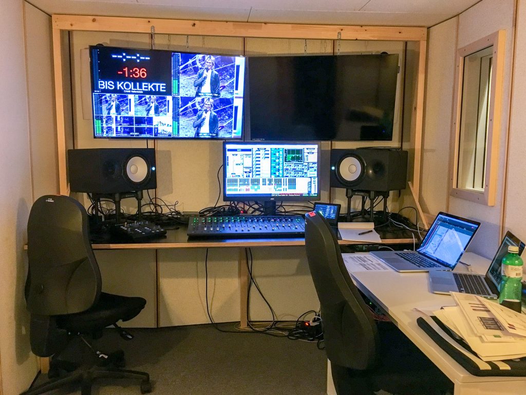
The ICF recording studio where I do mixing for live video and internet broadcasts for is, shall we say, small. Due to its small size and the presence of multiple large screens, it can become quite warm, despite fans to help cool it.

ICF Recording Booth

To remove a source of heat generation, I moved the Avid E3 Engine outside and on top of the booth, a change that both made it quieter and much cooler. (Note, we use a separate console for recording our bands in the studio, so the E3 fan noise doesn’t cause any problems as it is normally powered off.)

Placing the device outside though means I cannot as easily flip the power switch to power it on. To get around this limitation, I did some research and found that I can power the device on using the Ethernet Wake-on-LAN protocol.

Avid E3 Engine

To remotely wake the E3 engine, you need three things:

  1. A computer that is connected to the same Ethernet network as the E3 engine. If VLANs are in use, they must be on the same VLAN.
  2. The MAC address for the engine. The MAC address is available under the Options > Devices tab and right-clicking on the E3 engine image.
  3. The IP subnet address of the network. (Optional,  depending on the software used.)

Software for remotely waking the E3 engine.

There are several software packages available to send the special Wake-on-LAN Magic Packet.

Mac

  • Wake On Lan by Depicus (Mac App Store, $1.99)
  • Remote Desktop  (Apple, $79.99) – Also useful for controlling the S3L-X remotely.

Windows

Command-line

For those comfortable with the command-line, a short Python script will also do the job. Save this script somewhere as wakeonlan.py and make it executable with chmod +x. Myself, I keep a copy of the script in my ~/usr/bin directory.

#!/usr/bin/env python
# https://apple.stackexchange.com/questions/95246/wake-other-computers-from-mac-osx

import socket
import sys

if len(sys.argv) < 3:
    print "Usage: wakeonlan.py <ADR> <MAC>     (example: 192.168.1.255 00:11:22:33:44:55)"
    sys.exit(1)

mac = sys.argv[2]
data = ''.join(['FF' * 6, mac.replace(':', '') * 16])
sock = socket.socket(socket.AF_INET, socket.SOCK_DGRAM)
sock.setsockopt(socket.SOL_SOCKET, socket.SO_BROADCAST, 1)
sock.sendto(data.decode("hex"), (sys.argv[1], 9))

To wake my system, I call the  script like below, where 172.16.0.255 is the subnet of my network, and 00:90:fb:4a:13:9e the MAC address of my E3 engine.

~/usr/bin/wakeonlan.py 172.16.0.255 00:90:fb:4a:13:9e

Avid Stage 16

Unfortunately, the Stage 16 Box cannot be remotely power cycled without additional equipment. I haven’t set this up yet, but my plan would be to use one of the devices below to enable remote power on/off of the device.

HyperDeck multi-mono audio to surround

I recently made a recording with a Blackmagic Design HyperDeck 12G from an HDMI source which had 5.1 audio. Unfortunately, the HyperDeck recorded 16 independent mono channels, which meant that everything was on the center channel when I imported it into Final Cut Pro X. In addition, the C and LFE channels were swapped in the same manner that Media Express swaps them.

To fix the issue, I was able to use a similar command to what I used for fixing recordings from Media Express (see my post on that issue). The one change was using “-map 0:1” as the HyperDeck stores the video as Stream #0. This command has the nice side-effect of stripping the extra unused audio channels from the file, which also reduces the file size.

ffmpeg -i input.mov \
-c:v copy \
-filter_complex \
"pan=6c|c0=c0|c1=c1|c2=c3|c3=c2|c4=c4|c5=c5[out1]" \
-map 0:1 -map [out1] -c:a pcm_s24le \
output.mov

I also have some 7.1 sources, and for them I’ll be using a slightly modified version of the command.

ffmpeg -i input.mov \
-c:v copy \
-filter_complex \
"pan=8c|c0=c0|c1=c1|c2=c3|c3=c2|c4=c4|c5=c5|c6=c6|c7=c7[out1]" \
-map 0:0 -map [out1] -c:a pcm_s24le \
output.mov

Media Express C/LFE channel swap

Media Express by Blackmagic Design incorrectly swaps the C (Center) and LFE (low-frequency effects) channels on 5.1 surround material. This can be fixed using the ffmpeg command.

TL;DR

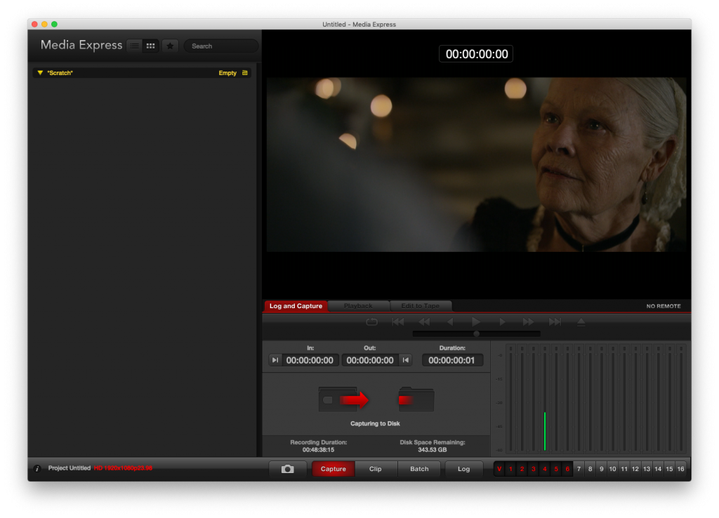
I recently purchased a Blackmagic Design UltraStudio 4K to do some recording from HDMI sources. Recordings must be made using the provided Media Express software, which is fine, except for the fact that the C and LFE audio channels are swapped in 5.1 material. As you can see in this screenshot, the spoken word coming through the center channel is on channel #4 instead of channel #3.

For reference

  • The standard 5.1 channel order for Wave files is: L, R, C, LFE, Ls, Rs
  • The non-standard Media Express 5.1 channel order is: L, R, LFE, C, Ls, LR

After significant troubleshooting, I found a solution using ffmpeg from the command-line to swap the C and LFE channels. The remaining steps require a working ffmpeg installation. I haven’t found a standalone version for macOS, but it is available via Homebrew.

HOWTO: Swap C and LFE channels on .mov file written by Media Express. Replace the input.mov and output.mov filenames as appropriate. The actual magic happens with the c2=3|c3=2 part of the –filter_complex flag.

ffmpeg -i input.mov \
-filter_complex "pan=6c|c0=c0|c1=c1|c2=c3|c3=c2|c4=c4|c5=c5[out1]" \
-map 0:0 -c:v copy \
-map [out1] -c:a pcm_s24le \
output.mov

If by chance you’ve already worked on a broken file with Final Cut Pro and want to fix the channel ordering on the exported file, the command is only slightly different—change the -map 0:0 to -map 0:1. FCP writes video as stream #0 and audio as stream #1, whereas ME writes audio as stream #0.

ffmpeg -i input.mov \
-filter_complex "pan=6c|c0=c0|c1=c1|c2=c3|c3=c2|c4=c4|c5=c5[out1]" \
-map 0:1 -c:v copy \
-map [out1] -c:a pcm_s24le \
output.mov

References

  • [Blackmagic Forum] Audio: LFE and Center channels being switched. I made a post on Jan 19, 2019 with similar information to that above.